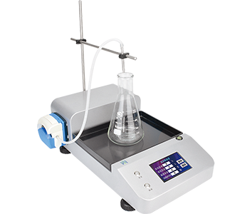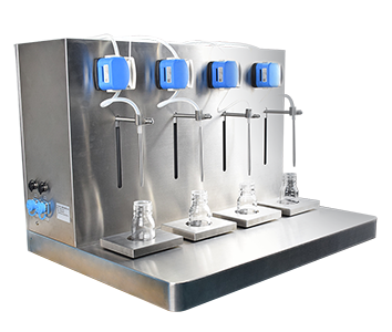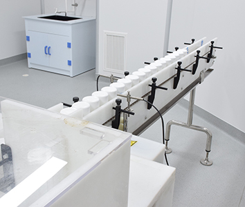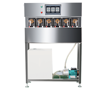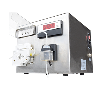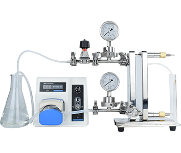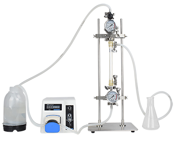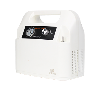

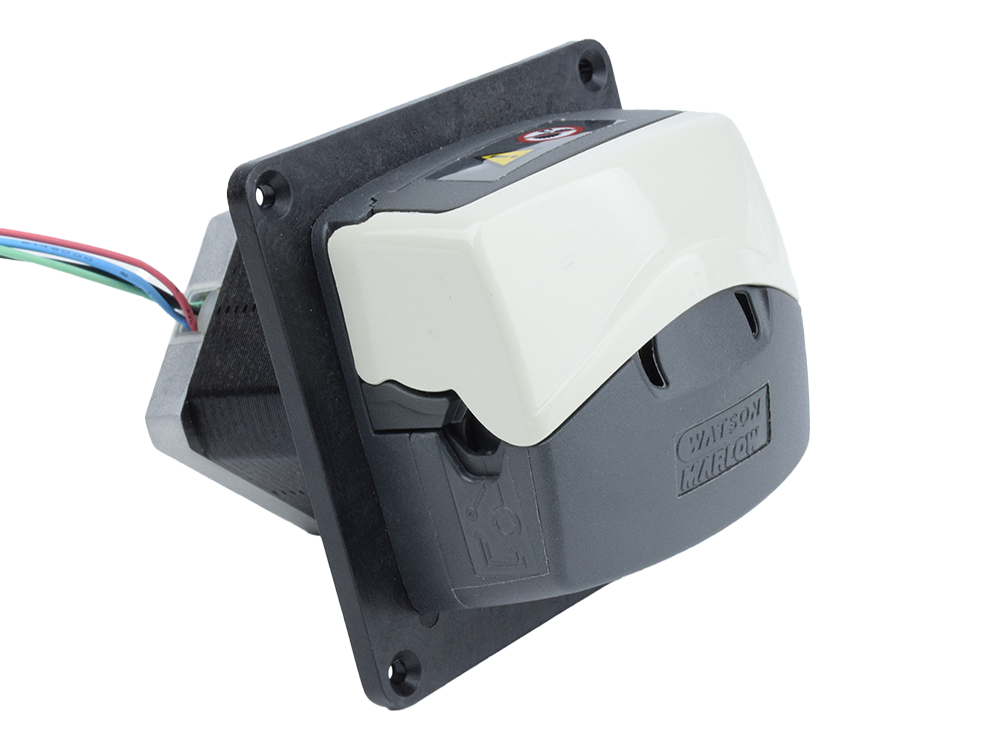
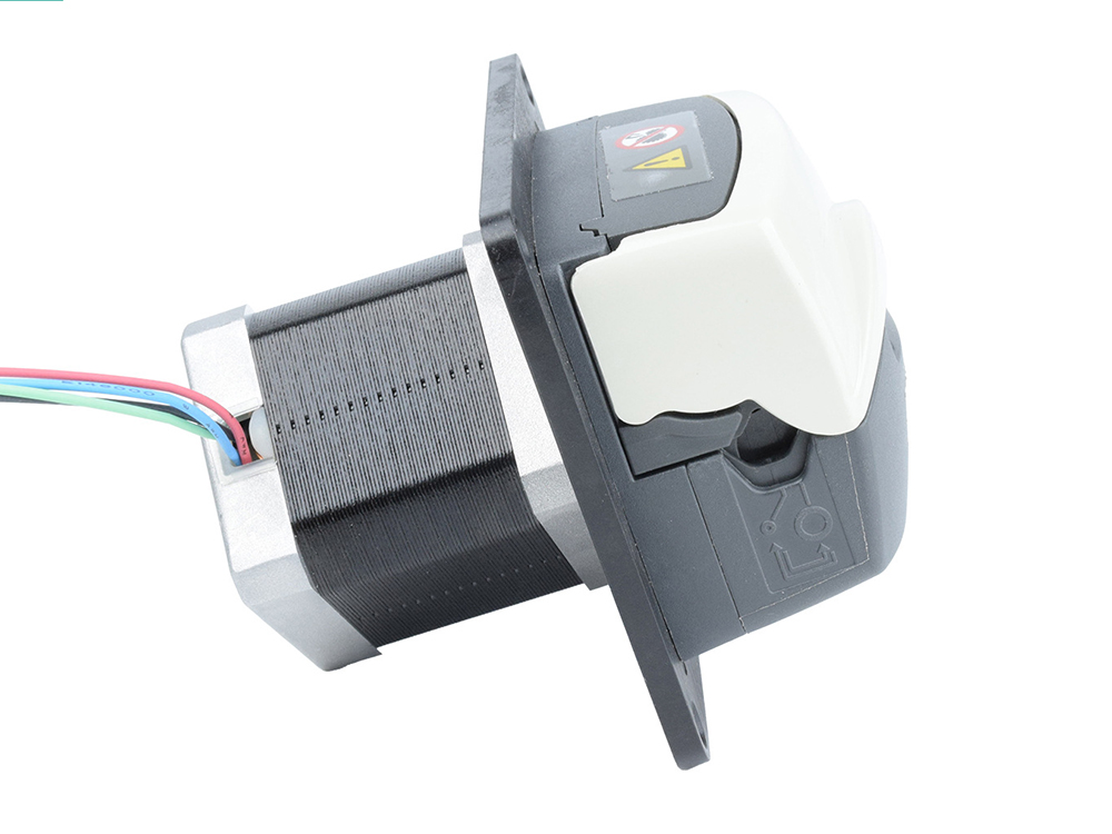
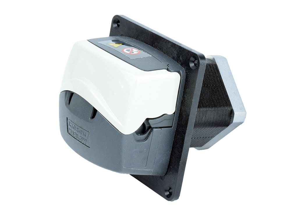
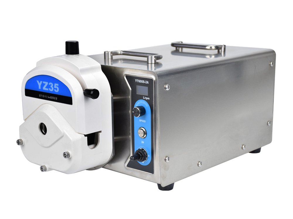
OEM Custom Peristaltic Pump Independently Developed by Moyan Electromechanical: This peristaltic pump is equipped with a WATSON-MARLOW 114D peristaltic pump head and a stepper motor. Speed range: Intermittent operation: 0–600 rpm; Continuous operation: 0–400 rpm Flow range: Continuous flow: 0–340 ml/min; Intermittent flow: 0–510 ml/min
1
340ml/min
600rpm
Share:


Dimension Drawing

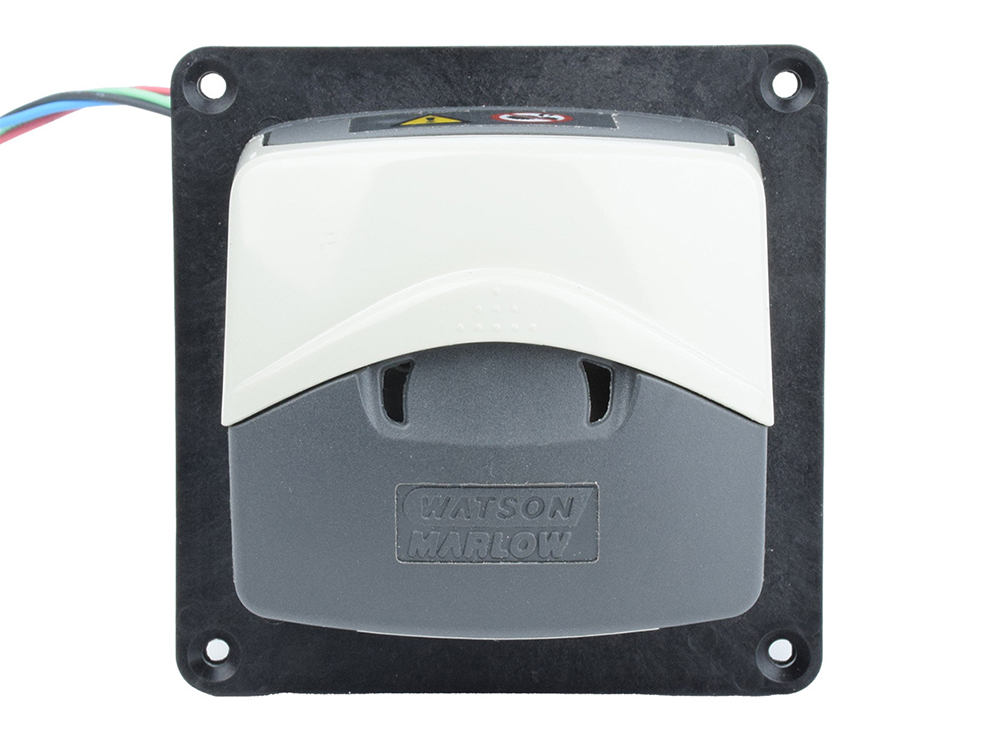
Pump Head Open Dimensions

Figure 3 114D Pump Head Flow Rate Curve
管孔内径(mm) | 0.5 | 0.8 | 1.6 | 2.4 | 3.2 | 4.0 | 4.8 | |
ml/rev | 0.02 | 0.04 | 0.14 | 0.29 | 0.47 | 0.67 | 0.85 | |
Flow Rate (ml/ min) | 30rpm | 0.7 | 1.3 | 4.2 | 8.7 | 14 | 20 | 25.5 |
60rpm | 1.4 | 2.6 | 8.4 | 17.5 | 28.5 | 40.5 | 51 | |
100rpm | 2.2 | 4.3 | 14 | 29 | 47.5 | 67 | 85 | |
190rpm | 4.3 | 8.2 | 26.5 | 55 | 90.5 | 128 | 160 | |
200rpm | 4.6 | 8.6 | 28 | 58 | 95 | 135 | 170 | |
350rpm | 8 | 15 | 49 | 100 | 165 | 235 | 300 | |
400rpm | 9.1 | 17 | 56 | 115 | 190 | 270 | 340 | |
600rpm | 13.5 | 26 | 84 | 175 | 285 | 405 | 510 | |
Pump Head Flow Rate Data Table

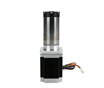
Motor and Driver Wiring Diagram

Driver Interface Terminal Definition
Interface | Description |
A+、A-、B+、B- | Motor interface |
VCC | Positive power supply (12~36V) |
GND | Power ground |
485_A、485_B | RS485 interface |
485_A、485_B | RS485 interface (for device cascading) |
A1 | 4~20mA current analog control input interface |
A2 | Input voltage acquisition port, or for external potentiometer (<3.3V) with AV & SGND |
AV | 3.3V output interface; for power supply when using external potentiometer with AV & SGND |
SGND | Analog input GND port |
S3 | Sensor 3 (3.3~5V compatible), connected to quadrature encoder A for closed-loop model |
S4 | Sensor 4 (3.3~5V compatible), connected to quadrature encoder B for closed-loop model |
S5 | Sensor 5 (3.3~5V compatible), connected to encoder Z for closed-loop model |
S6 | Sensor 6 (3.3~5V compatible) |
5V | 5V output (<100mA) |
SGND | Signal ground |
The RS485 interface supports cascading up to 32 slave devices.Pins S3, S4, S5, and S6 can be configured as inputs or outputs (I/O).The 5V output port can supply 5V power to external devices.
For the integrated closed‑loop model, pins S3 and S4 are factory‑assigned for connecting encoder A and B signals, and pin S5 is used for the encoder Z signal (if the Z signal is applied).
The 4–20 mA analog signal adjusts the speed within the range of 0–60 rpm.
The purple S6 wire and black SGND wire control motor start and stop.
The brown S5 wire and black SGND wire control motor rotation direction.
The analog input wire is the green A1 wire.
The analog power is supplied by the red 5V wire.
Note: The yellow‑green SGND wire for the analog signal must be short‑circuited with the black SGND wire for the power supply.
We pride ourselves on customer service and are committed to providing five-star support. If you have any questions about our products, please feel free to call or send an email to us.
Speed1 to 650 rpm, reversible
Flow Rate≤13000ml/min
Speed controlmultiturn potentiometer
Speed0.1 to 100 rpm, reversible
Flow Rate≤380ml/min
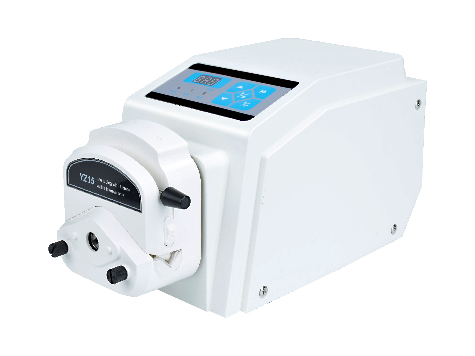
Display 3-digit LED displays current rpm
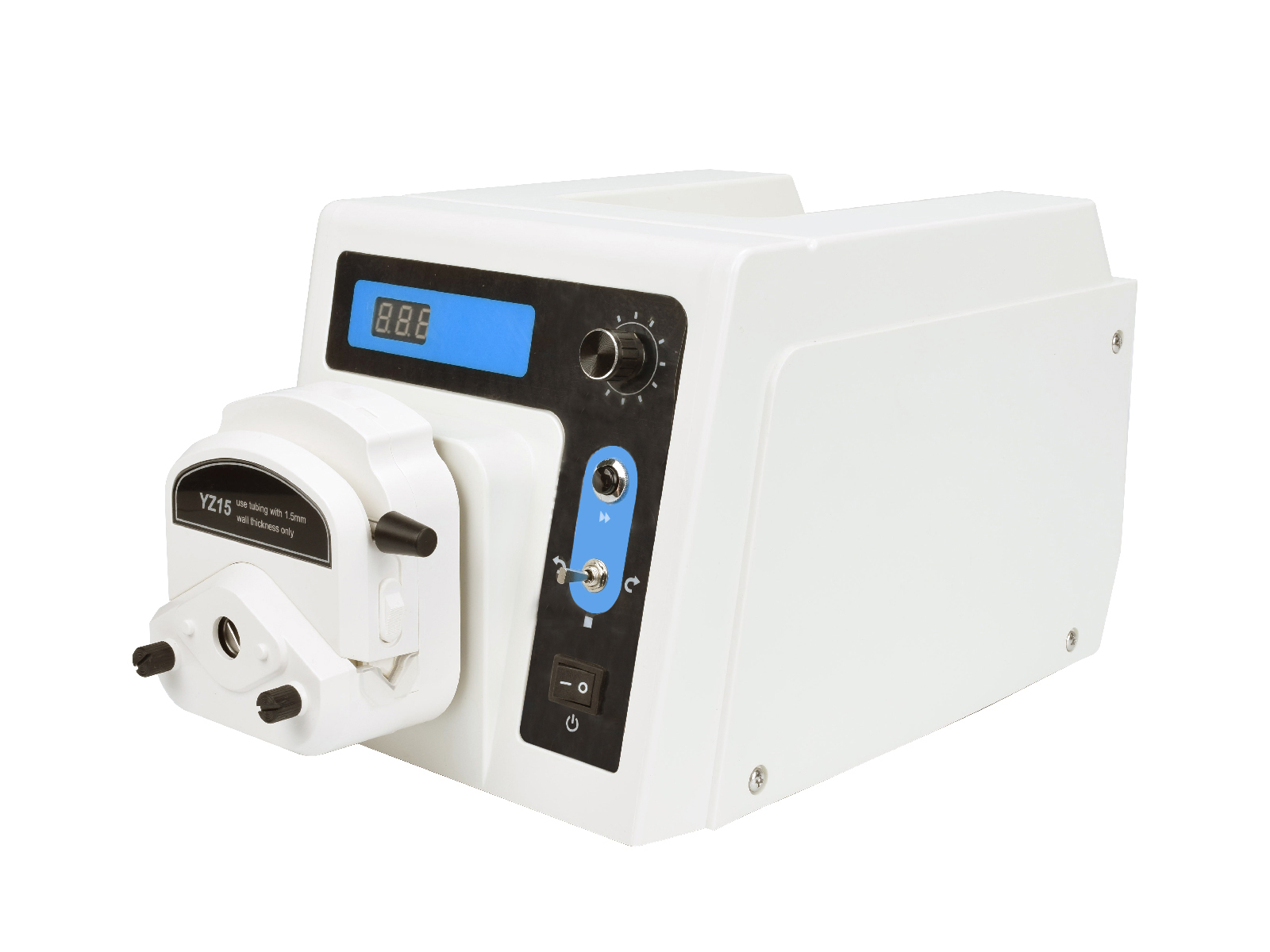
Speed1 to 600 rpm, reversible
Flow Rate≤2200ml/min
Display 3-digit LED displays current rpm
Number of Channels1
Flow Rate Range120ml/min
Rotational Speed Range100rpm

Professional Integrator of Automated Liquid Handling System Equipment
Room 102, 1st Floor, Building 3 No. 666 Songhuang Road Qingpu District, Shanghai China
1st Floor, Building A, Chuangye Center No. 295 Jingxiu Street, Jingxiu District Baoding City, Hebei Province, China